Reference Materials for VDM-10 (Dragon Raptor) & T10-DDM (Zero 10X) (& other T series)
Reference diagrams and spare parts for a range of popular models of:
- T10-DDM such as ODM of Zero (10X), Dragon (Hunter X10) & MiniWalker and other ODM's.
- X11-DDM such as ODM of Zero (11X) and Dragon (X11) and other ODM's.
- VDM-10 such as ODM of Dragon (Raptor), Apollo (Ghost), Carbon (Oxy), Bolzzen (Dynamo/Gladiator), e-Glide (Mach 10) and other ODM's.
- and to lesser extent the single motor models T8 and T9 such as ODM of Zero 8 and 9, Dragon X9.
These models share the same QS-S4 communications protocol system which is also adopted on similar class VSETT models. Controllers are often branded Kyesang.
This image below was exported from the high resolution PDF factory diagram. The PDF works well with Google translate, the images below won't due to lack of detail.
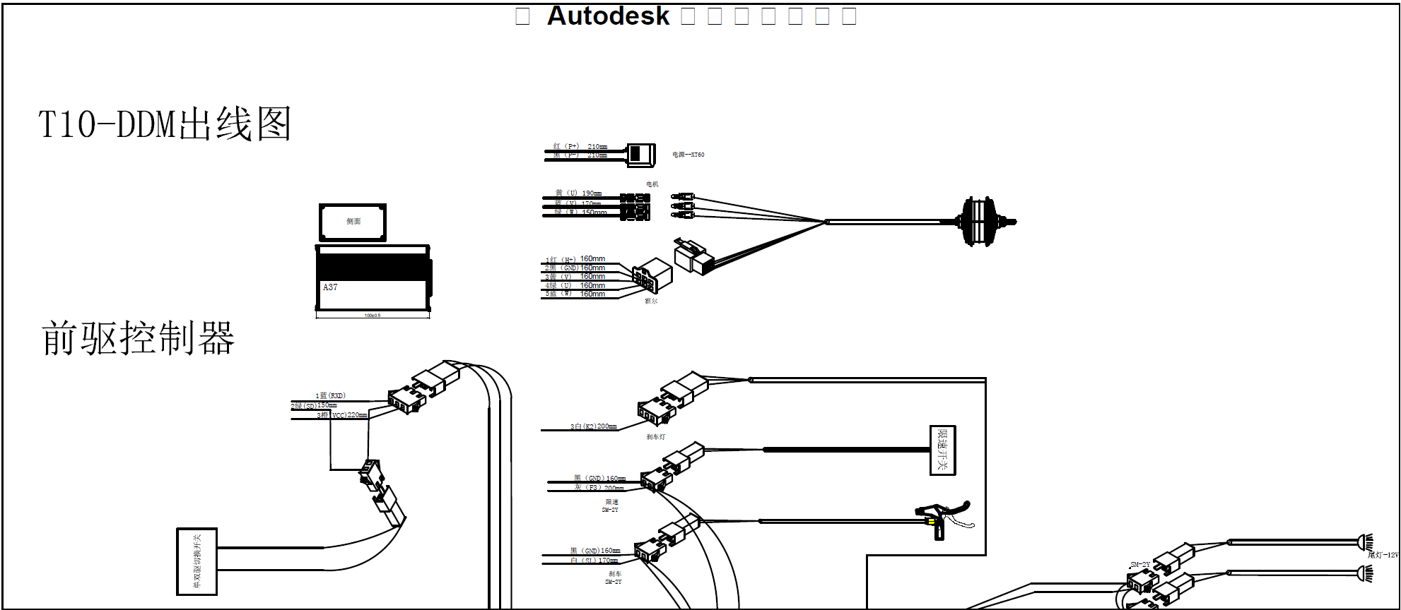
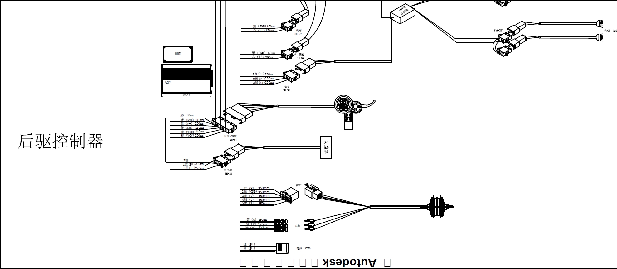

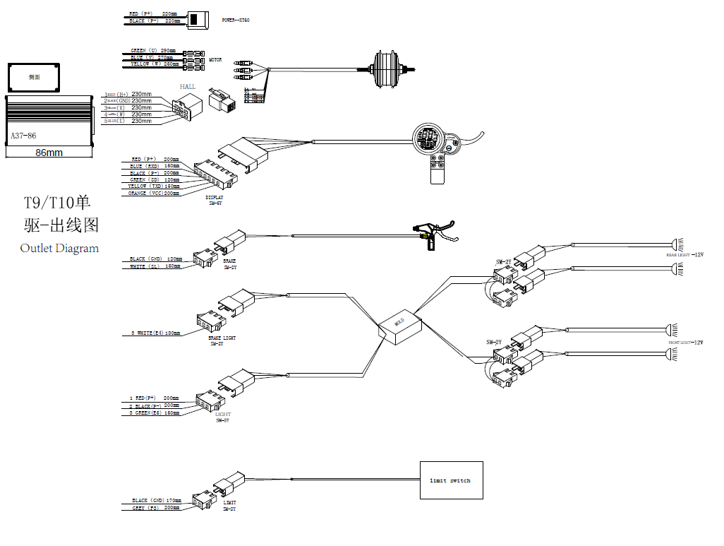
The single motor diagram, T9/T10:
JST SM 6-pin Throttle/Display connector - Showing colours on communication cable, translated.

QS-S4 M8 5-pin connector pinouts as drawn observing the presented face of the display cable. Note colours on wire attached to QS-S4 may differ.
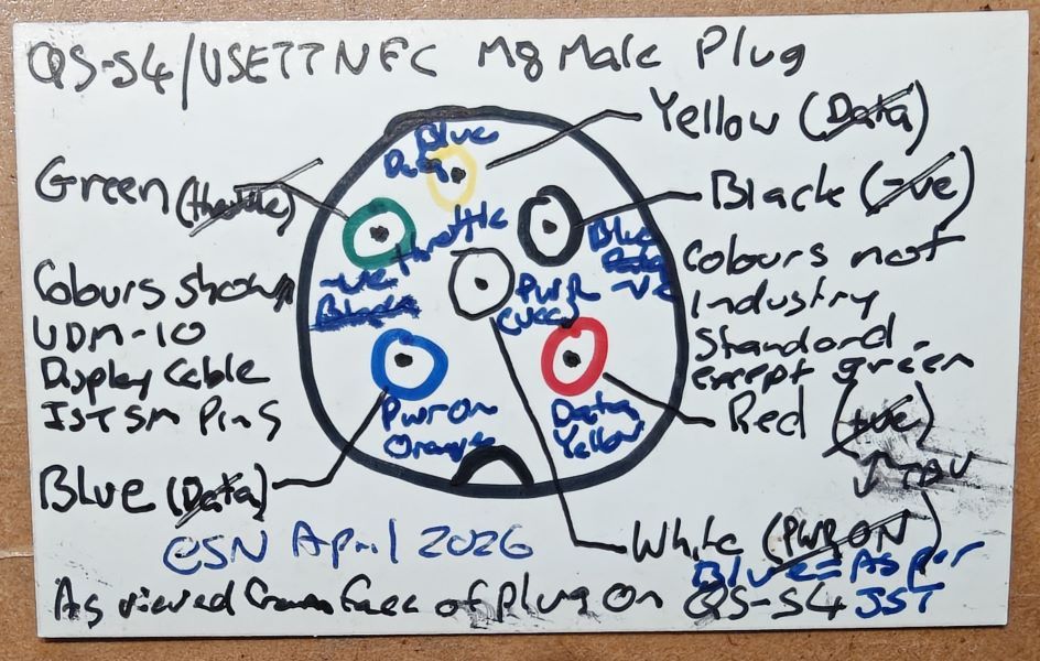
End-to-end colours: QS-S4 typical colour as viewed from face of M8 male plug (display cable as observed JST SM female, controller as observed JST SM male):
Yellow -ve
Green (green, green) Throttle | Black (black, black) Data +ve
White +ve (blue, - orange)
Blue PWR-ON (blue, orange) | Red (red, yellow) Data -ve
Notch
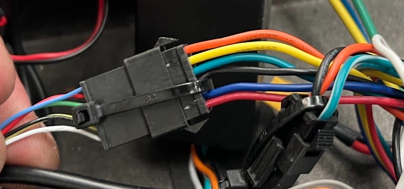
Image shows the colours across the pinouts on the JST receptacle from this display cable (left) and the matching colours on controller plug (right). It is observed that the colours chosen in this display cable (in all Zero's and VDM-10's) need be aligned / matched as shown below. The only pinout that has a colour match is the green (throttle). Courtesy the late Kevin Sanders
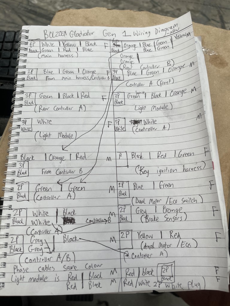
Wiring Diagram showing connectors and colours as-built on Bolzzen Gladiator Gen 1 from the late Kevin at Scooteroo Australia in Perth:
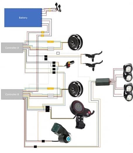
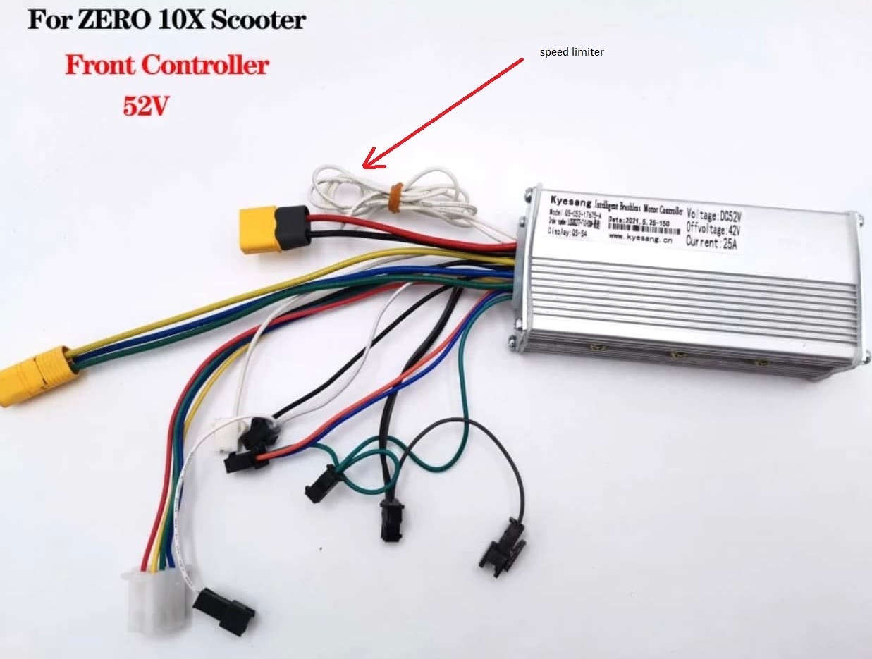
Some diagrams amongst AliExpress controller sellers:


This diagram shows the speed limit implementation wire. When the loop is joined, the limiter is active (typically 25kim/hr but likely also impacts the power/torque, similar to adopting half way between gear mode 1 and 2).
Display prices in:AUD