Heads-up: order fulfilment is taking a short hiatus effective 25th Feb for eSN2026#JP-CN resuming mid-March | Now Club | Group Ride Guide | Workshops: BSG / On The Run
Reference Materials for NAMI Electric
Comprehensive artifacts including wiring diagrams and triage flowcharts for NAMI models such as Burn-e and Klima.
Facebook communities:
Official: NAMI Electric BURN-E/BLAST/KLIMA/ Electric scooter
Alternative: NAMI Electric Scooters Worldwide Group (excellent featured posts)
Alternative: NAMI NATION FOR BURN-E, KLIMA, BLAST LOVERS
Wiki / Repositories:
NAMI-Viper GitHub repository by Krzysztof Hajd
NAMI published materials:
Michael Sha's shared common information Facebook post
NAMI published improvements
NAMI Tail Light (suit Burn-e, Klima and Blast)
Videos showing how it looks on Burn-e:
Specifications February 2023
From Michael Sha around the time of the inaugural 40Ah


3rd party specifications (and components within)
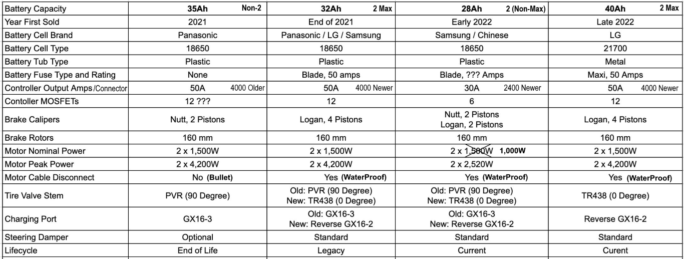
Steven Chan at NAMI Electric Scooters Worldwide Group has put together a table showing the different variants of Burn-E. A few corrections and clarifications have been added (e.g. 28Ah motor power). The marketing name reflects Australian region product names (some regions progressed to a "3"). /Connector designates nameplate prefix in white marking on enclosure (reflecting watts) and motor wire plug controller designation relates to the older bullet style or newer "quick disconnect" waterproof modular plug. Diagrams for that plug are on this page designation BM-JH26-09M (male plug on wire attached to motor).
Known / common issues.
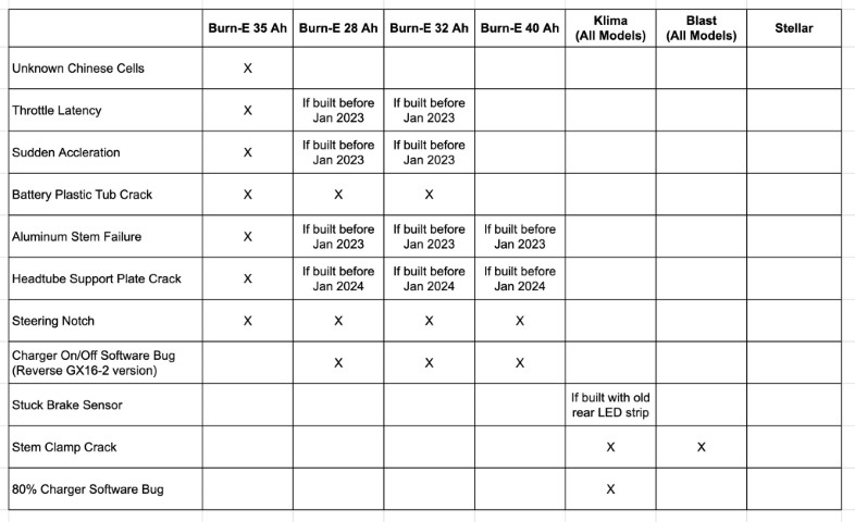
A handy reference from Steven Chan at NAMI Electric Scooters Worldwide Group showing known issues. This reference helps troubleshooting common problems (approx. 50%), most have a resolution pathway that is well known and documented on various Facebook groups. This extract from Jan 2024 remains current September 2024. It is not a complete, exhaustive list of all known common issues.
FAQ's from NAMI Electric Scooters Worldwide Group (featured):
Klima Brake Sensor Issue
Well documented at NAMI Electric Scooters Worldwide Group
Stuck Brake Sensor issue applies to Klima if built with old rear tail light (led strip). Often resolved by uplifting to NAMI Tail Light.
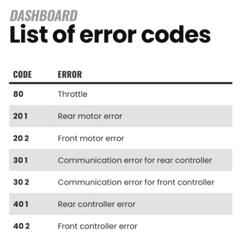
Error codes from Burn-e user manual.
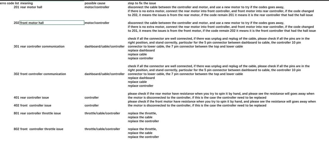
Guidance for steps to resolve errors arising from error codes:
From Jonathan Bernabe in response to 301 error discussion potentially provided by a regional distributor.
Troubleshooting Flowcharts from Steven Chan. Two examples shown below, these can often be intermittent and challenging to resolve, pathways are not exhaustive but a good start.
201/202 (Motor error)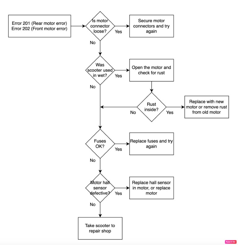
301/302 (Communication error)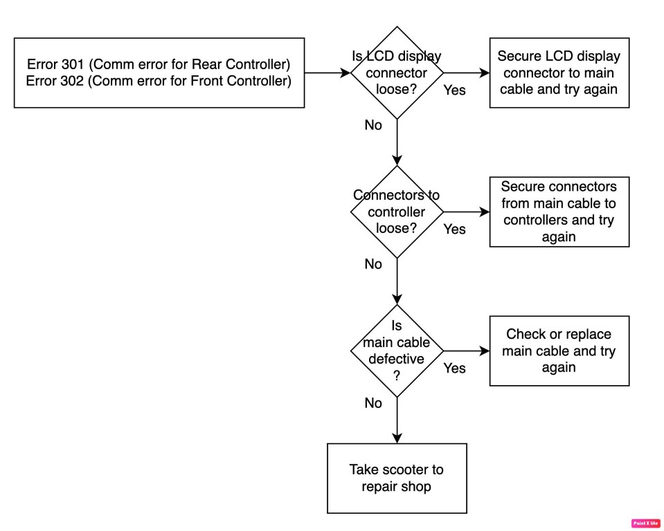
Regarding 301/302 (communication) errors, all but the oldest of NAMI controllers feature a black single-core medium gauge cable with a bullet connector. This interconnects the two controllers to form a good earth, preventing harmonic distortion and potential voltage, which can introduce 30x errors. Typically, controllers with this interconnect need to co-reside with another with the same earthing interconnect so they are grounded. Co-existing a newer controller with an older without can throw 30x (communication) errors. Two without tend to be OK. It is also observed that often power needs be isolated from both controllers after disconnecting of any controller cables. Assumed there is some initial start-up auto-calibration which may be influenced on the grounding interconnect. Additionally, 301/302 errors can be "burnt" into the dashboard and persist, even when there are no conditions present to warrant the error. While renewing dashboard is often a first troubleshooting step, doing this may inadvertently render the replacement dashboard to throw and persist 301/302 error, rendering replacement inoperable. A better approach would be to fit a 301/302 dashboard into a known, good working scooter to test, in conjunction with renewing the root cause component that initiated the error (which could be Dashboard, controller, motor etc). Some other considerations for 30x errors are discussed here.
The long and short is that it's good practice to isolate the controllers from the battery just prior to testing any renewal or reconnection and be mindful Dashboard can persist 301/302.
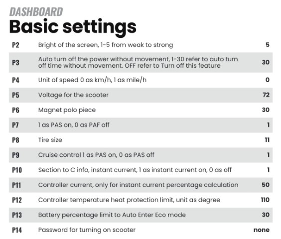
P Settings (basic settings) from Burn-e user manual.
P Settings (advanced settings) from Burn-e user manual.
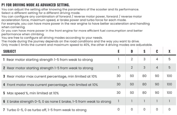
It is understood E brake strength does not vary, regardless of level 1-5 setting. 0 is none, 1-5 is on, there is no weak to strong. It is believed this is by design to prevent excessive regen and associated increase in voltage.
More P-setting discussion at: https://www.facebook.com/share/p/7qJPpsTpbSUxVYsz/
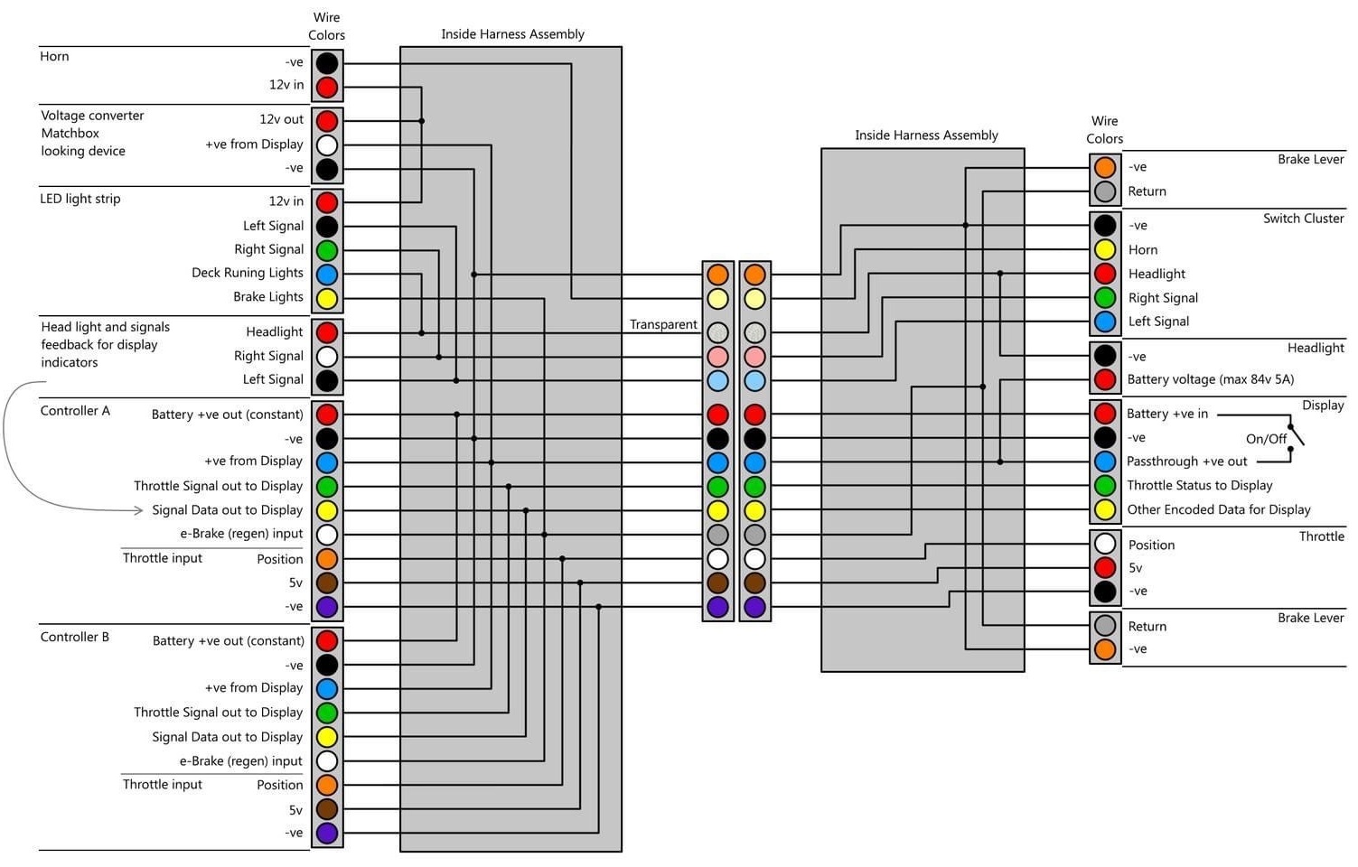
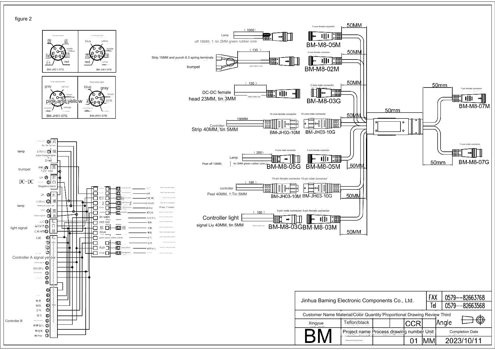
Main Cable Wiring Diagrams for Lower (Shorter) Single light Connector Version (shown on left) and Upper (Longer) for non-NFC (shown on right):
This factory diagram was translated to English and subsequently re-rendered by Brobic Vripiat 3rd April 2022. The diagram shows the older 5-pin light and horn switch connector ("Switch Cluster") which subsequently progressed to 6-pin with the introduced centre pin being +ve.
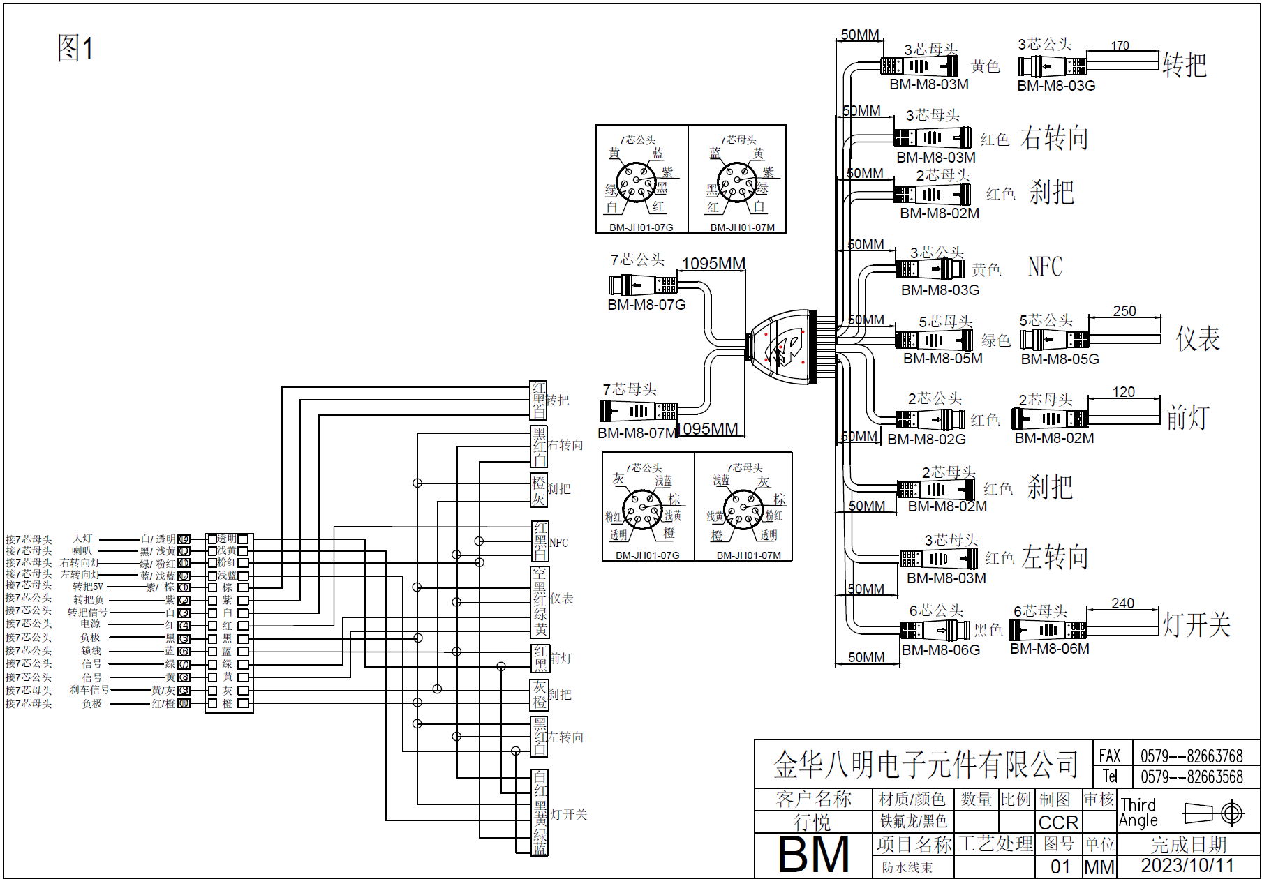
Main Cable Wiring Diagrams for Upper (Longer) for NFC and optional Front Turn Signal (shown in first image #1) and Lower (Shorter #2) - Dual light connector version (shown in second image):
Contrasted to diagram above, the upper cable introduces the 6-pin light and horn switch connector (rather than 5-pin), along with connectors for NFC reader and front turn signal. Page 2 shows the shorter main cable that has two 5-pin connectors for concurrent rear tail light and battery led strip.
Pinouts for connectors are shown as viewed from connector rear (i.e. as if you were forming wire connectors to the pins on the back of the connector).
Note designations on these diagram are ambiguous whereby M = Female, G = Male. For avoidance of doubt, reference the drawing plug shape.
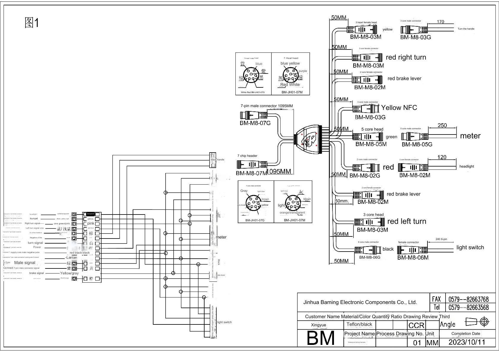
Partially translated diagrams of above:
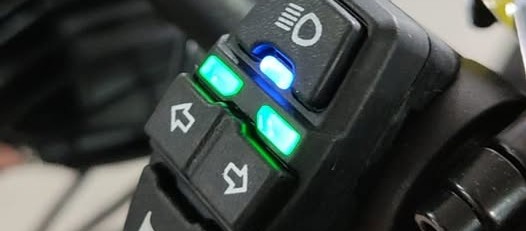
LED status lights on turn switch instrumentation
You can learn more about this newer switch and associated 6th pin that was introduced on the newer main cables by reading this post at NAMI NAMI Electric BURN-E/BLAST/KLIMA/ Electric scooter. The inaugural switch used a green 5 pin connector and it had phantom LED that would no illuminate due to absence of a 6th pin in the center of the plug which was introduced in V1 main lines.

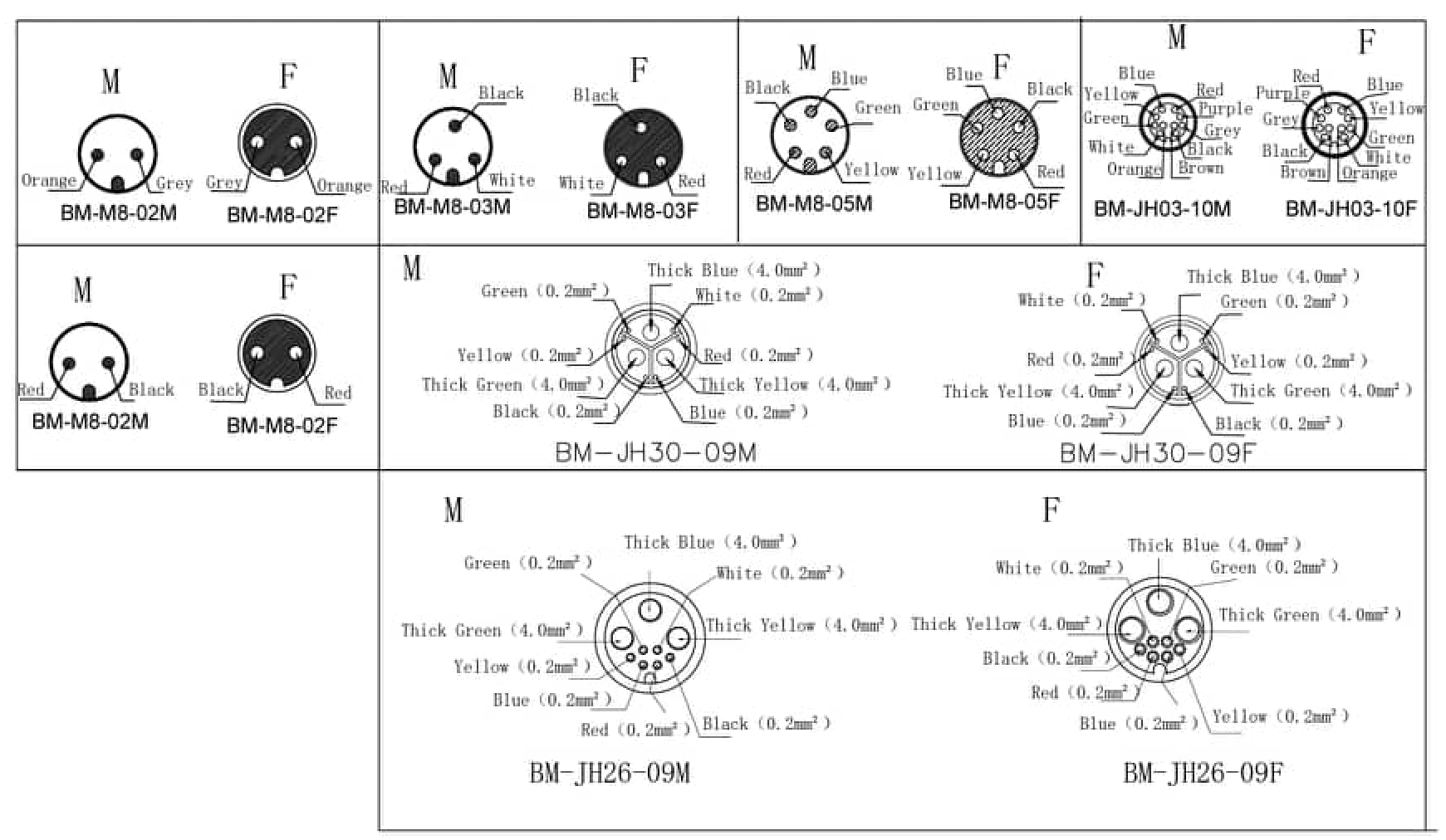
Wire colour to position diagram
From NAMI-Viper GitHub repository by Krzysztof Hajd, extracted from BMING diagram.
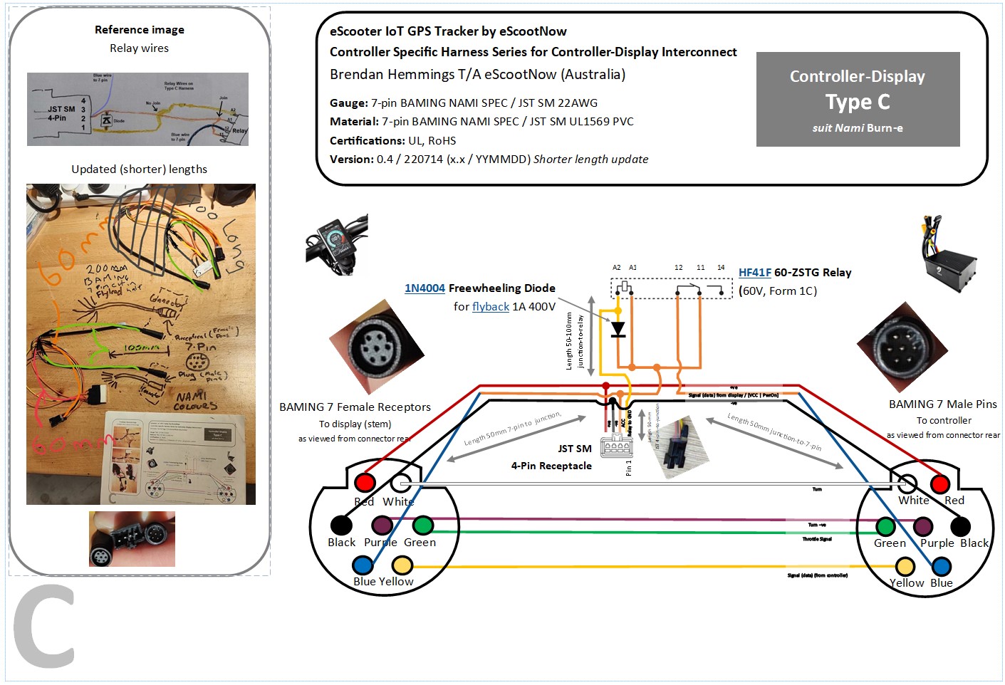
eScootNow Type C harness for IoT GPS Tracker as published in NAMI Electric Scooters Worldwide Group showing purpose of the pins.
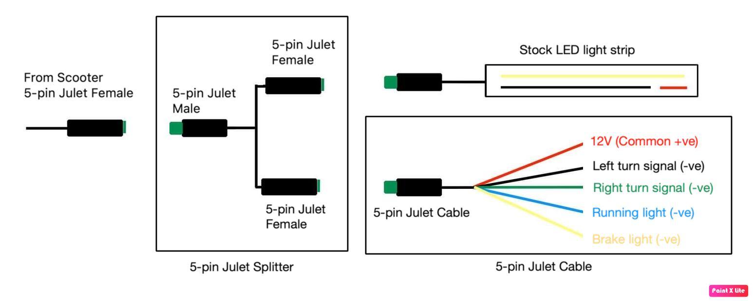
How to wire aftermarket brake lights, running lights and turn signal lights
This article includes re-rendered Burn-e diagram and 5-pin Julet Cable and the accompanying post with video. Note -ve switched (+ve common) system which requires PNP state change circuit.
eBrake / regen foot bypass switch wiring diagram
By Michael Spring as posted here in NAMI Electric BURN-E/BLAST/KLIMA/ Electric scooter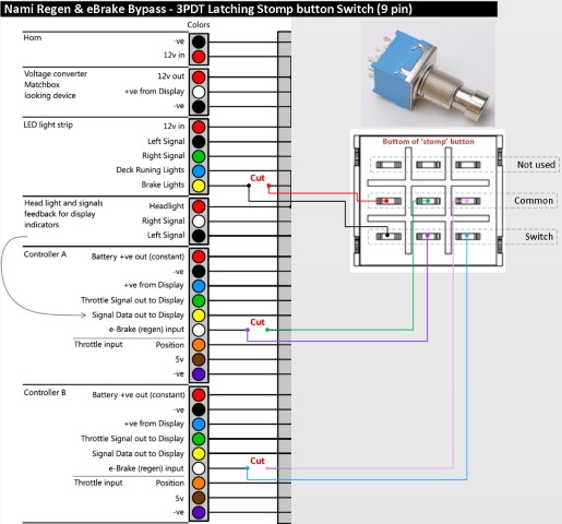
Wiring for Aftermarket Light and Horn Switch.
For replacing the factory original with 3rd party instrumentation like that of eSN's TurboTap, the "Better switch cluster" on the NAMI-Viper GitHub repository by Krzysztof Hajd. Note this adopts the older 5-pin connector, not newer 6-pin.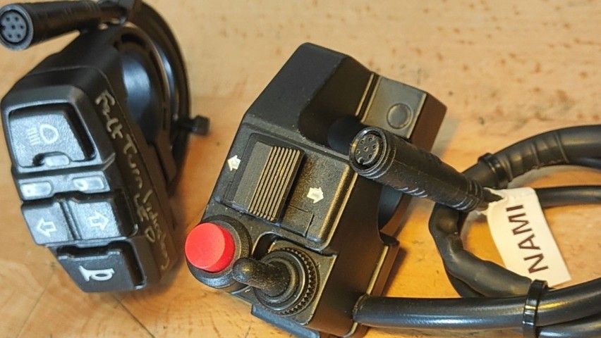
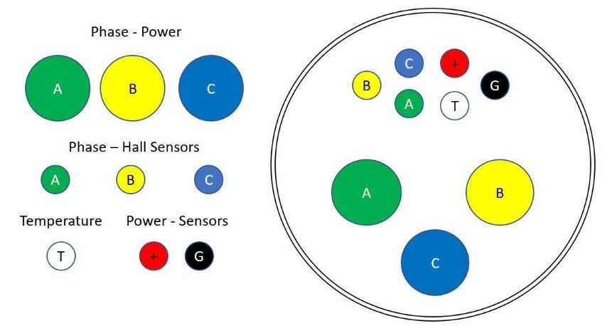
Burn-e Water Proof Motor Connector (Quick Disconnect) pinout courtesy Qiyuan Zhou (matches the BMING diagram further above which is marked designation BM-JH26-09M):
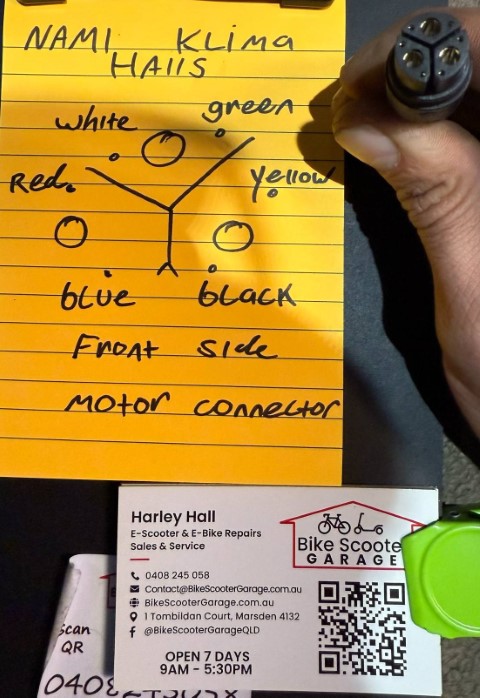
NAMI Klima Motor Connector (courtesy Harley Hall). This matches the BMING diagram further above which is marked designation BM-JH-30-09F:
Electric System upgrade
New Dashboard (brighter), NFC, LED light switch, main cable, tail-light, horn cable with internal capacitor, with supported controller offers 3 second M hold speed limiter and PWR button hold for walking mode.
NAMI Burn-e cable system and electric parts. Note, very early Burn-e models did not use Water Proof integrated connector, they use Bullet connectors..
Motor bearing replacement (Burn-e)
Bolt sizes and torque from NAMI Electric Scooters Worldwide Group.
Appears to be a corrected version of diagram at NAMI-Viper GitHub repository by Krzysztof Hajd, initially published by Michael Sha.
Display prices in:AUD
